From time to time I will describe cases from expertise that I do.
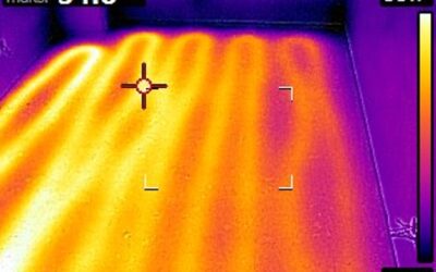
Below is an example of a terrible design and even worse execution of a very good idea to use floor heating of tunnels where a delicate agricultural production is conducted. The area of the floor heating is ... 0.22 ha, i.e. 2200 m2 ! Huge..
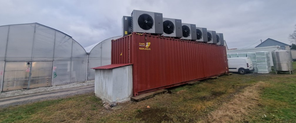
In the design phase, the heat demand for heating the temperature inside all six foil tunnels to 20C was not calculated. This is the first time I have come across a central heating installation project in which the heat demand was not calculated. As a result, the 12 pumps in two cascade generates negligible heat power in relation to the demand. As a result, 60 tons of heating oil are used for one and a half heating seasons (which cost about PLN 350,000) in order to maintain the temperature of +20C inside the tunnels, which is crucial for the investor's delicate agricultural production.
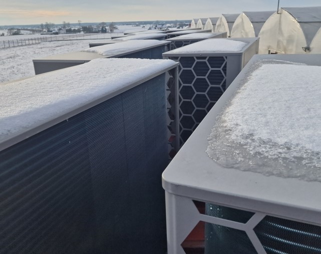
The second very good idea was to build in a heat source from a cascade of air heat pumps. Then we have a perfect combination of a floor heater and a heat pump. This is what people are taught in engineering studies.
Unfortunately, the contractor built two cascades of six (!) heat pumps each. 26,712 hours passed between the day of signing the work completion protocol and the day of reading the controllers. Let's make an optimistic assumption that the heating season in connection with agricultural production in foil tunnels is half a year. This means that the pumps should have worked 13,356 hours. They should have, but they didn't. For example, pump P1 worked 43,859 hours, and the difference between the extreme values of working times was more than 11 times. This is the result of building a cascade of heat or cooling sources in a quantity greater than the optimum, which is usually three.
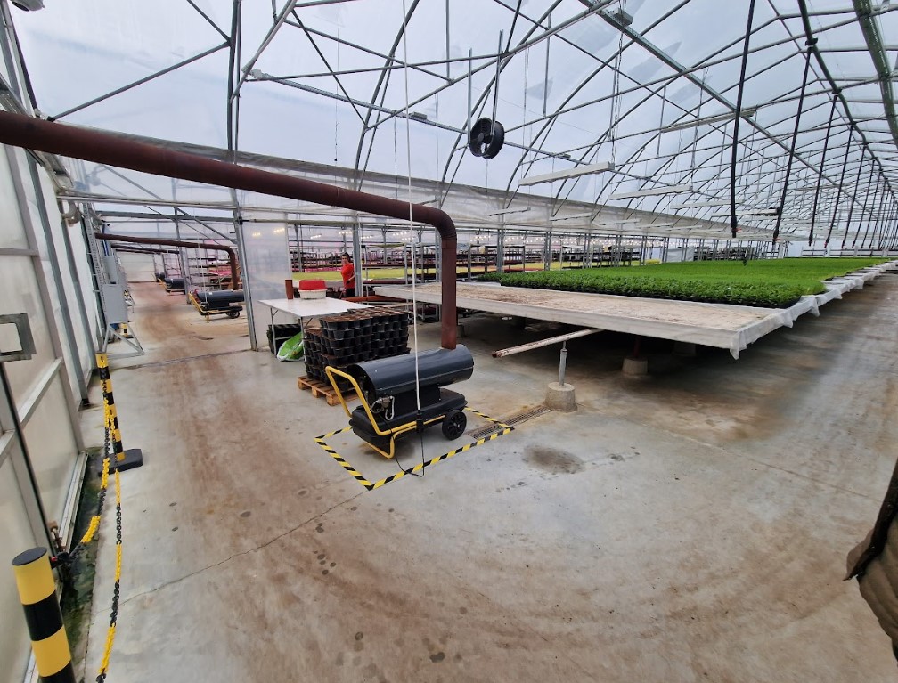
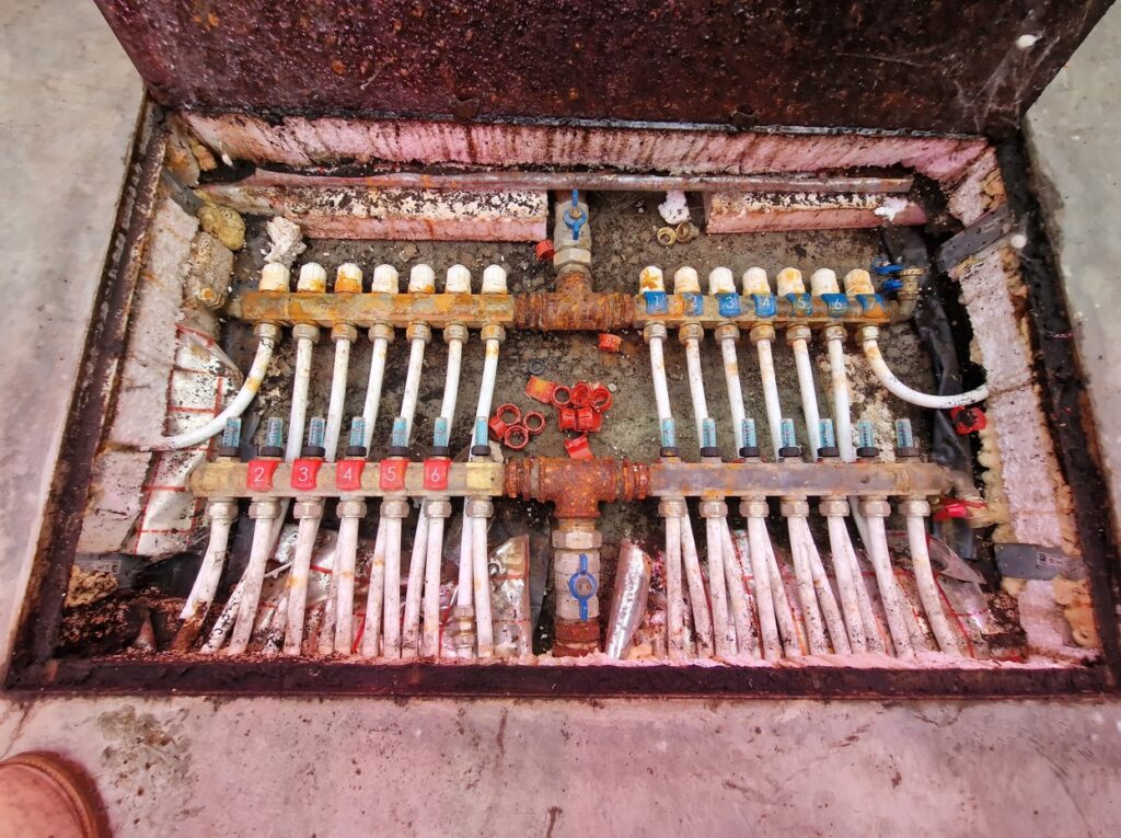
This is what the floor loop distributor mounted horizontally inside the foil tunnels looks like after two seasons of operation.
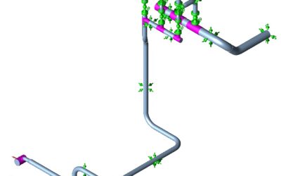
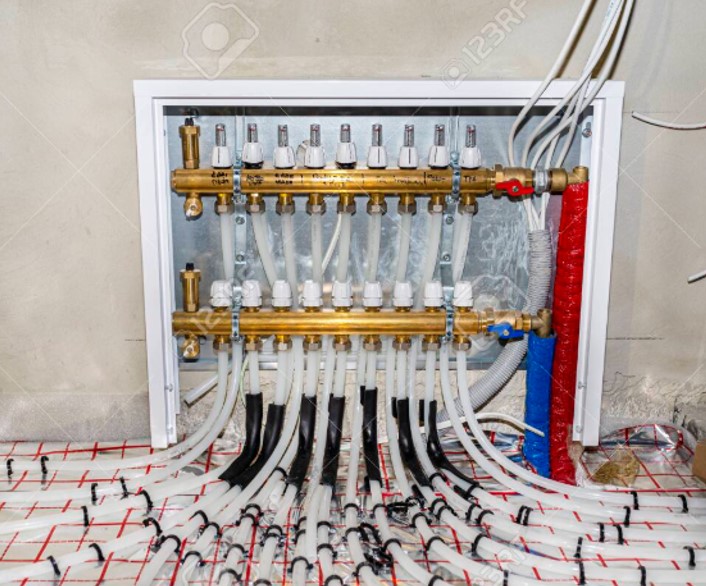
This is how it should look and how it looks in thousands of normal implementations.
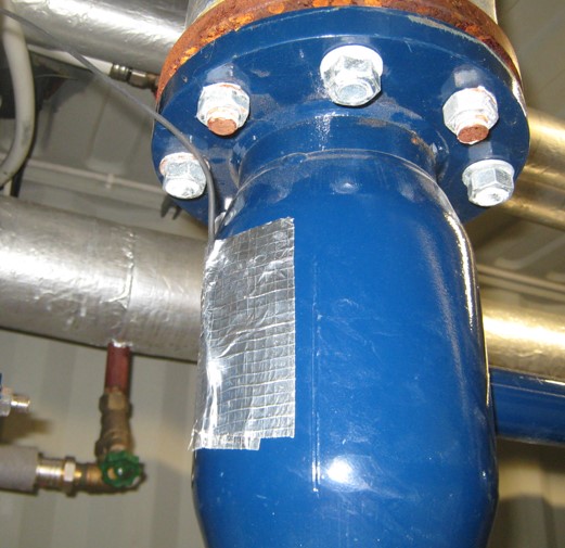
An example of mounting a temperature sensor on a valve housing using the proverbial spit.
The installation of all heat pumps was designed on the roof of one container. As a result of this solution, the minimum distances from building partitions were not maintained. The heat pumps are placed face to face. For such a configuration of heat pumps, it is not the minimum service space that is crucial. It is the unobstructed freedom of ventilation air flow for heat exchanger ventilation. A conservative solution should be adopted and the minimum distance should be set at 2C, i.e. 160 cm. The measured distance is 45 cm, so it is ~3.5 times smaller.