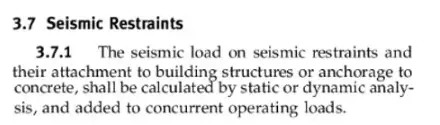
In this thread, I've briefly strayed into statics modules. In this post, I'll address the displacement of pipeline supports during an earthquake. In B31E, there's a clear requirement (shall) to perform static or dynamic calculations.
In B31.3 it is also presented in this way, except that there is no mention of the movement of supports during an earthquake.
EN 13480-3, however, uses a more lenient statement (should). Such analyses are typically described with the acronym SAM – Seimic Anchor Movement, although they apply not only to fixed points but also to supports with line guise and line stop functions. Of course, they do not apply to rest functions.
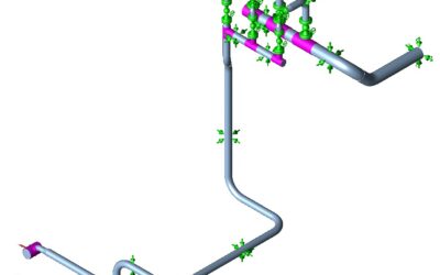
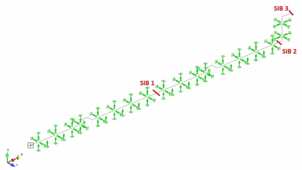
First, I'll return to the SAM static analysis, which is the most common approach. The decision to use statics or dynamics is left to the designer. The model looks as follows: The entire structure is divided into three SIB (Seismic Interface Barrier) segments, the horizontal section being the viaduct, and the vertical section being the approach to the building.
Pipe specification: DN 100 (4'), 6.02mm (STD). The medium is water. A horizontal seismic acceleration of 0.2g and a vertical seismic acceleration of 0.1g was assumed. The vertical section height was 8m. The temperature was 100C and the pressure was 1 MPa. The seismic displacement was determined according to applicable rules, which I will not describe now: NSEW overpass level = 5mm, NSEW building entrance level = 40mm. No seismic rotation at the supports was assumed.
To verify that the correct directions have been chosen, it's worth viewing the displacement results. If all is well, the SIBs will change their displacement direction.
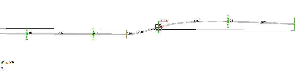
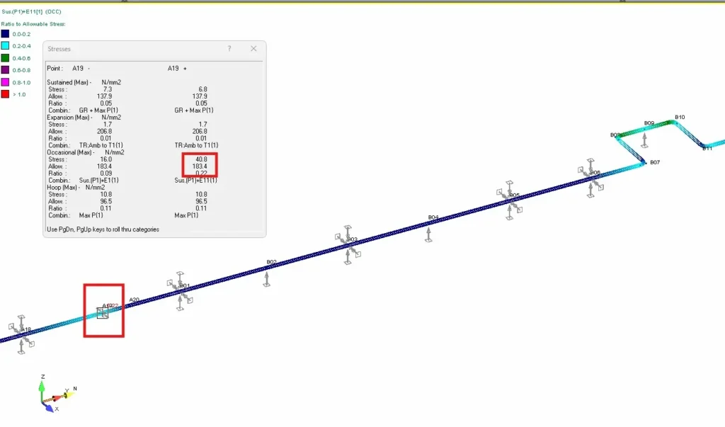
The result of the static SAM analysis in AutoPipe for the fixed point upstream of SIB 1 is as follows. The code stress is 40.8 MPa.
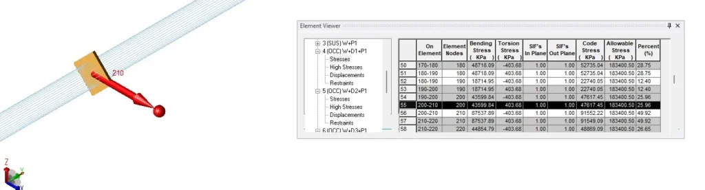
Regarding Caesar, the situation is less convenient. All seismically movable supports must be equipped with Cnodes. For the same point, the stress was 47.6 MPa.