This section presents simulations for various load combinations of galvanizing bathtub 50 mm thickness
Load case
This section presents simulations for several different load combinations
- Operation temperature +450C
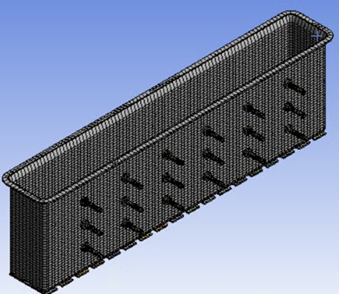
The FEM Model
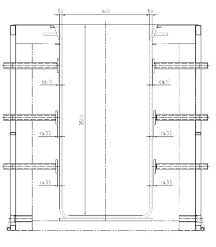
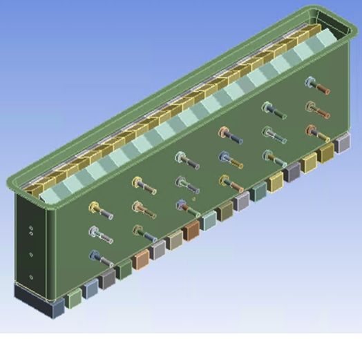
The galvanizing tank is constructed of 50 mm thick steel sheet, grade S235JR+N / 1.0038, according to the PN – EN 100025 – 2 /1/ standard. The tank model and its support scheme were created based on the drawings below. The zinc brick models were created based on data from a manufacturer of grade Z1 zinc (HCM SHG 99.995). [1] Huty Cynku „Miasteczko Śląskie” S.A.[2]
[1] https://hcm.com.pl/oferta/#cynk-z1
[2] https://hcm.com.pl/
The base model
For this purpose, a basic model of all the essential elements of the bathtub and the zinc brick charge was created, shown below. Depending on the needs, this model will be cut into smaller portions to complete a given simulation batch within a reasonable timeframe, i.e., no longer than one day.
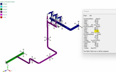
Tools for assessing stress state
Principal stresses were used to assess the stress level. These stresses, designated S1 to S3 in the simulation, have positive or negative values, indicating the nature of the material's work at a given point. Sign convention: positive: the material is in tension; negative: the material is in compression. Bending of the walls also occurs, during which one side of the wall is stretched (positive stress) and the other side is compressed (negative stress). Depending on which side of the tank is viewed (inside or outside) or at which point in the cross-section, different values and signs will be observed.
Principal stresses are perpendicular stresses acting on the walls of an element rotated so that the shear stresses disappear.
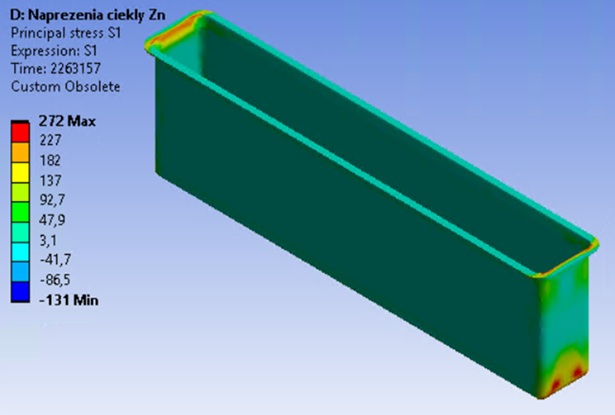
S1 (Maximum Principal Stress) is the most "positive" stress. It shows the maximum tension at a given point. Even if S1 is negative, it means the element is compressed from all sides, i.e., a so-called triaxial compression state occurs. Maximum positive values (red/yellow zones) indicate that these areas could fracture under tension. Blue zones are where the "maximum" tension is actually compression (or close to zero).
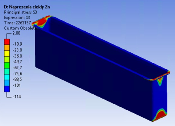
S3 (Minimum Principal Stress) is dominated by blue (negative values). It shows how strongly the material is being crushed, especially over supports.
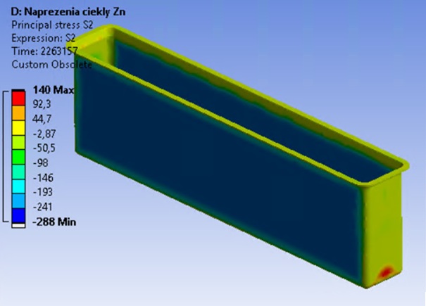
S2 (Middle Principal Stress) is useful in shell structures because a flat sheet metal surface typically experiences a so-called biaxial stress state. This means that the material is being pulled or compressed in two directions simultaneously. A good analogy is a stretched drum membrane. One might think that since S2 is "medium," it can be ignored, but this is not the case. S2 is crucial in calculating the equivalent stress. Steel fails through shear (crystal slippage), and shear depends on the difference in stress. If S1 is large and positive, and S2 is large and negative, the equivalent stress will be large. If S1 and S2 are both large and positive, meaning stretching occurs in multiple directions, the equivalent stress will be smaller.
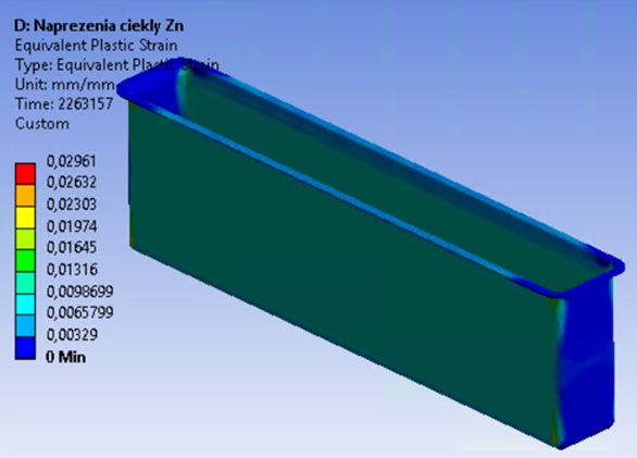
It is common to confuse principal stresses with Huber's reduced stresses.[1]The latter is always positive because it actually reflects the scalar energy of shear displacement. The reduced stress is excellent for assessing the strain in steel, as it indicates the moment when the steel transitions into the plastic state. In the language of linear algebra, a single principal stress is a stress tensor matrix. Looking at the principal stress field, we see a scalar number derived from the tensor field.
[1] Maksymilian Tytus Huber (1872–1950), an outstanding Polish scientist. In 1904, he published the hypothesis of the specific energy of shear deformation.
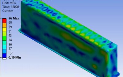
The results0C
The first principal stress, S1, represents the maximum tensile stress. The highest values occur at the upper flange (flange) and at the corners. This is the result of stress concentration at the points of geometry change and the effect of hydrostatic pressure from the zinc, which "pushes" the tank. The value of principal stress S1 suggests that the material has likely exceeded its yield point and is flowing in these areas.
The second principal stress S2 acts perpendicular to S1 and S3. It usually describes the stresses along the plane of the wall [1]Negative values (blue) on the long walls suggest that in certain directions the material is being “squeezed” by thermal expansion constraints from the rigid bottom.
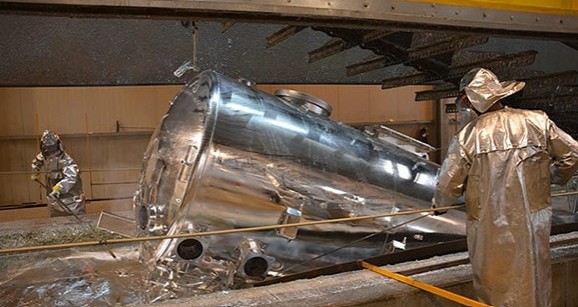
The third principal stress, S3, represents the maximum compressive stress, which in this case primarily represents compressive forces. High compressive stresses can lead to local buckling of the walls if they are too thin, although in this case, this effect is unlikely to occur. However, it can occur in the final phase of the bathtub's service life, when the wall is much thinner than the initial 50 mm. Unfortunately, this combination is not a matter of dispute, as the failure occurred when the bathtub was new.
[1] In pipeline design, this is the most important circumferential stress