When modernizing old installations, exceedances on the nozzles very often occur. Usually, on such occasions we hear: "Why do you want to strengthen the nozzle on the equipment? After all, the installation is working several dozen years and nothing has happened"The secret lies primarily in the much lower stiffness nozzle-equipment-foundation system than it is assumed in pipe stress programs, i.e. in the phenomenon compound stiffness.
Let's consider the composite stiffness itself. In pipeline technology, it is used in the case of equipment on flexible support structures, such as those shown below. The stiffness determined for the equipment's nozzles in isolation from the entire device is a mistake. In an ideal situation, the stiffness of the nozzles should be issued by the manufacturer. Of course, this is a very rare case. If someone is interested in how to determine the stiffness of the nozzle themselves, I encourage you to read Part I - HERE
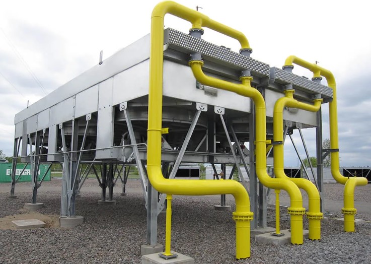
Due to lack of time I will not model such a complex support structure, which can be seen in the above photo. Let's assume that we have a much simplified support structure of the camera, as in the drawing below. For the description of the concept of complex stiffness it does not matter.
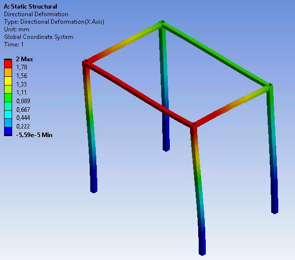
From the above figure, the directional stiffness of the equipment's frame can be determined, e.g. KFx = 1 kN/mm. We proceed in this way for all six degrees of freedom. For example, in the X direction, the stiffness KNx = 3 kN/mm.
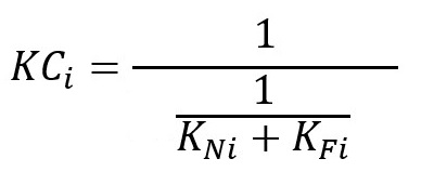
Compound stiffness nozzle-equipment-foundation system is the equation of a simple relationship. For each degree of freedom, it is the reciprocal of the sum of the reciprocals of the stiffness of the stub pipe and the frame.