Why does sheet metal thickness affect the risk of brittle fracture? The key to understanding this phenomenon lies in two concepts: plane stress state (PSN) and plane strain state (PSS). This refers to what happens to the material in the thickness axis during tension. In thin sheets, only the PSN occurs, during which the material in the zone of maximum stress is free to deform in the thickness direction (because it is negligible compared to the other two dimensions), causing a transition to a plastic state in the form of a so-called "neck." This deformation absorbs very high energy and allows the steel to flow plastically before final fracture. This is ductile fracture, which presents warning signs.
In thick plates, PSO occurs, during which the core of the element is "trapped" by the enormous mass of surrounding steel. The material inside wants to contract but physically cannot. This results in a triaxial stress state – the third axis in the thickness direction. In this state, shear stresses are blocked, which are responsible for "slippage" in the crystal lattice, i.e., plasticity. Since the steel cannot flow plastically, stresses increase until they exceed the tensile strength of the crystal lattice itself. This results in brittle fracture at far the lowest permissible temperature. The steel breaks suddenly and with a tremendous bang, and with minimal energy absorption, just like glass. Therefore, thicker plates force designers to choose steels with a higher guaranteed fracture energy. This rule only applies to structures operating continuously at low temperatures (bridges), so it does not apply to galvanizing tanks operating at the temperature where creep begins.
How do you assess what value of work of fracture is sufficient? The Charpy impact test is a test dynamic on a notched sample. From it, the fracture work is determined, which is included in the standards. In turn, the most important material feature from the point of view of fracture mechanics, i.e. the critical stress intensity factor at plane strain PSO (KIC), is determined under the conditions statycznych using a fatigue crack. There is no purely analytical formula that connects these two values. However, since K studiesIC are very expensive and time-consuming, empirical relationships have been developed that allow estimating KIC Based on the cheaper and faster Charpy test. Thanks to these formulas, having studied the work of fracture, the designer can estimate the KIC and calculate the critical defect size (e.g., a microcrack) that will lead to the destruction of the structure or apparatus. In other words, fracture mechanics will not answer the question of whether a low fracture energy value at room temperature is the primary cause of failure. However, it could answer whether, for a given fracture energy, a given initial microcrack can develop into a full crack through the thickness of the tank sheet. However, we will not have such data.
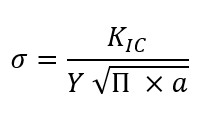
Why doesn't the work of fracture alone determine the breaking stress? The yield strength tells us at what stress a material will crack. idealny (without defects) will begin to permanently deform. The work of fracture, on the other hand, tells us how much energy the material can absorb once it has has a defect (notch) and we hit it dynamically. The breaking stress is proportional to KIC and to the size of the notch according to the generally known formula:
The relationship between fracture toughness and yield strength is usually inversely proportional. There used to be a relationship for structural steels that the harder and more durable the steel, the more brittle it is. Today, with sophisticated heat treatment methods and alloying additives, this relationship is no longer so obvious. There is no single, magic formula. You have to follow the path: KV – KIC – determining the defect size – calculating the breaking stress. In the power industry, there is a strictly observed rule regarding the commissioning and shutdown of pipelines operating at critical parameters, which are relatively evenly heated along the circumference of the internal surfaces. In the case of a galvanizing tank (despite being a non-pressurized device), this rule is absolutely crucial for the safe operation of the device. This is due to the fact that very intense heat sources are distributed in only a few locations. Temperature unevenness leads to uneven deformation, which results in an uneven stress field. To minimize these unevenness, stops should be made to standardize the gradients.
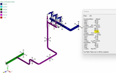
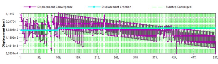
The figure below shows a graph of the simulation convergence over time. It shows that the greatest convergence problems occurred in approximately the first 20% of the time. What does this mean? Although the simulation is hypothetical, it does illustrate a possible failure scenario. During the initially uneven heating (i.e., the first hour or two), a deformation state (buckling of the tank's side surface) occurs, which bends the tank's arcs. The arcs could have been at temperatures of several dozen degrees Celsius, but their impact strength was still low enough that the stresses resulting from the deformation led to brittle fracture. Unfortunately, the author has no hard evidence for such a scenario, and never will.
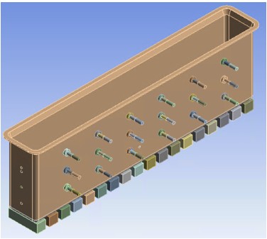
Model of the galvanizing tank used for simulation.
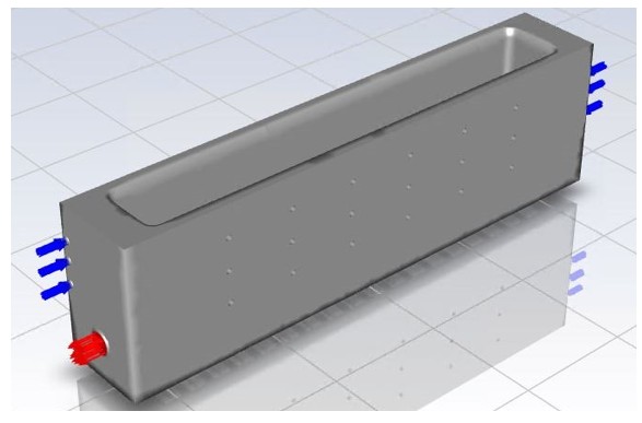
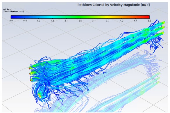
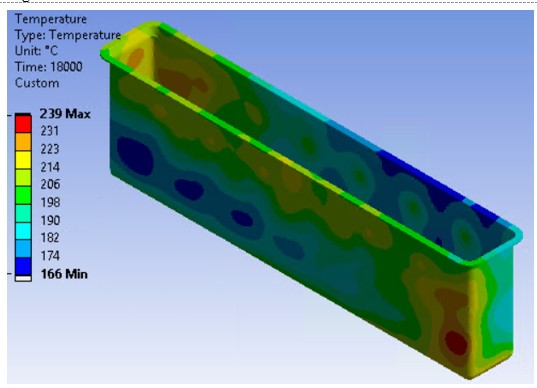
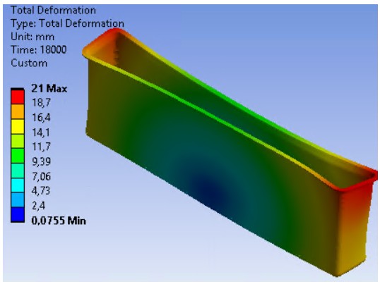
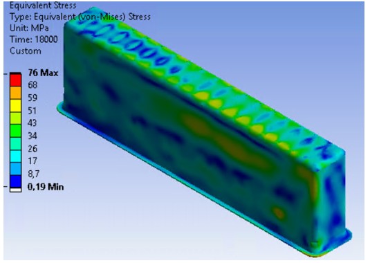
Results for the 5th hour of heating, i.e. for 10% of the entire heating time of the bathtub.